
The SOARA 224.100 Repeater became intermittent and stopped transmitting a few months ago. I finally made an appointment with the Laguna Beach water district to visit the site on May 28th.
Once on site, I quickly determined that the repeater had no power output. Keying the repeater did engage the transmitter, but nothing was heard even at close proximity to the repeater. I disconnected and removed the repeater radio from the shelf and took it home to troubleshoot the problem.

Once on the bench, I took the cover off, a time consuming task given it has so many screws that hold the top cover on!

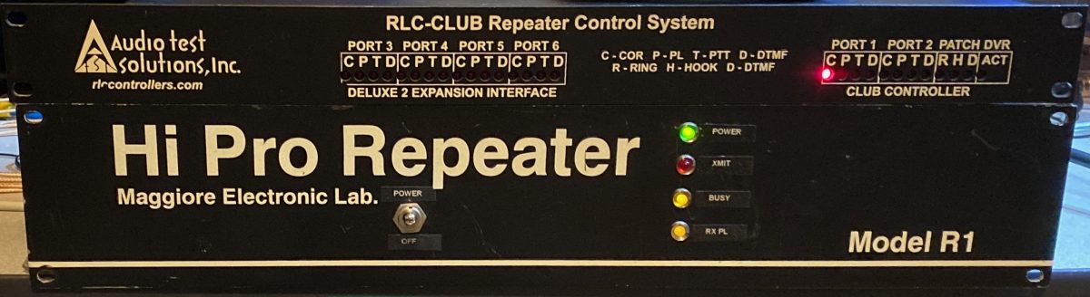
The receiver and transmitter are in separate shielded sections with the center section of the cabinet available for a repeater controller, PL encoder/decoders and cabling. The transmit side consists of a Maggiore Hi Pro EV1 Rev F. transmitter/exciter and Hi Pro PAV-1 Power Amplifier.
My first thought was that the PA output transistor might have failed since it’s a part that is put through a lot of stress from heat and high current. I disconnected the exciter from the PA and wired a test transmitter to the input of the PA. It worked fine. I followed the alignment procedure and was able to obtain a clean 20 watts of output power into my service monitor.

The output of the exciter was only a few milliwatts when it should be about 3.3 watts. Measuring voltages through the filter stages, I found the voltage on the base of a transistor in the first buffer stage was very low. I removed the exciter board to make it easier to perform further testing and repair.
When removed from the chassis, I had to apply 13.8 volts to both the oscillator and subsequent buffer/multiplier/amplifier (PTT keying) stages. Once I did this, I noticed a large increase in power into the service monitor.

Once I went through the alignment procedure described in the service manual, I was able to obtain about 4 watts output from the EV1 transmitter.
Now that I had a working exciter/transmitter and PA, I reassembled everything back into the chassis.
Measuring the power output, it was back down to a few milliwatts output. Measuring the two 13.8 volt supply lines to the transmitter while grounding the PTT line, I found that the oscillator voltage was fine, but the PTT keying line was only 3volts! The obvious problem was the PTT relay. For some reason, Maggiore had used a 28VDC relay instead of a 12 volt relay.

I fabricated a small PCB with a relay and flyback diode. Luckily I had just purchased some automotive quality relays to fix a problem with the central locking system in my Toyota and I had a spare Fujitsu 52ND12-W relay.

Fujitsu 52ND12-W automotive relay used for PTT keying
Grounding the supply side of the relay energizes the relay and passes 13.8volts onto the keying line of the transmitter.
The output power was now 20 watts. I hooked the R1 up to a repeater controller and adjusted the audio levels. Lastly, I grounded the transmit PL enable line and adjusted the deviation of the PL encoder.
A few days later, I re-installed the repeater at Temple Hill. I added an RCA “Y” cable to connect the PL decoder logic output to the PL encoder enable input. This causes the transmit PL encoder to be activated any time a user’s input PL is received and decoded. The purpose is to allow listeners with CTCSS / PL Decode enabled to only hear users and not courtesy tones or repeater IDs.
Leave a Reply