Terminal & AccessPoint modes enable you to use your IC-9700, IC-705, or ID-52 to communicate over the network, without using RF. Terminal and AccessPoint mode use either Callsign or Zone Routing. Callsign routing was more popular before reflectors and linking became available. In the early days of D-STAR, callsign routing enabled a ham who is in range of a gateway-enabled D-STAR repeater the ability to specify the callsign of the remote party they wanted to speak with. By entering a callsign into the URCall field, the system routed the transmission to the last place the specified callsign was heard. Upon receiving the transmission, the remote party would press RX->CS to load the calling stations callsign into their URCall field and establish the return path. Now that most gateways are connected to dplus/dref reflectors, callsign routing might result in everyone on the reflector connected to the remote gateway hearing only one side of the QSO. Newer radios enable the use of callsign routing without the need for a local gateway-enabled repeater system.
This guide explains how to use terminal and accesspoint modes within the Icom and dplus infrastructure.
Icom Reference Guides
| RS-MS3A Instructions | https://www.icomjapan.com/support/manual/1609/ |
| RS-MS3W Instructions | https://www.icomjapan.com/support/manual/1610/ |
| RS-MS3I Instructions | https://www.icomjapan.com/support/manual/4237/ |
| Guide to the DV Gateway Function | https://www.icomjapan.com/support/manual/3414/ |
| Firmware Update IC-9700 | https://www.icomjapan.com/support/firmware_driver/?keyword=IC-9700&open=tab2&type=5#download_result |
IC-9700 / IC-705
firmware UpdaTe
Make sure you are running the latest firmware for your radio. The latest Firmware is available through the Icom Japan Support Web Site
Network Setup
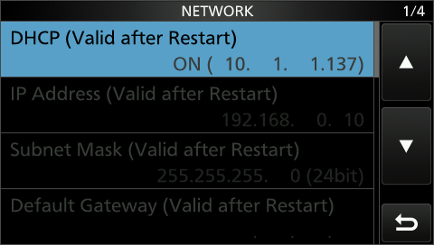
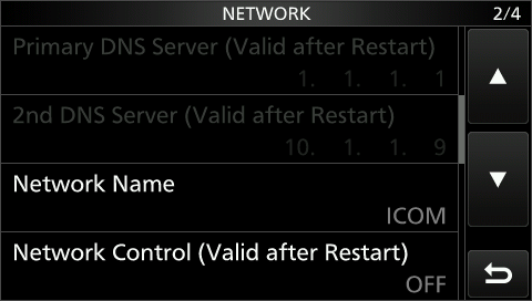
Before using Terminal or AccessPoint Mode, you must connect your radio to the Internet using Wifi (705) or a wired LAN (9700) connection. Under the Menu->Set-Network configuration screens, you configure the usual IPv4 information: DHCP or Fixed IP, subnet mask, default gateway, Primary DNS server, Secondary DNS server, network Name, and other settings.
To use Terminal or AccessPoint Mode, you can use either the Internal networking capability of your radio, or you can use an external connection to an Android Tablet or Windows computer.
Registration
To use D-STAR, you must register on any gateway in the system. A special registration gateway called REGIST is available to everyone.
You can check your D-STAR registration status here.
One nice feature that REGIST has and other gateways don’t is a password reset feature. The service is supported by multiple volunteers who tend to registration and assistance requests quickly.
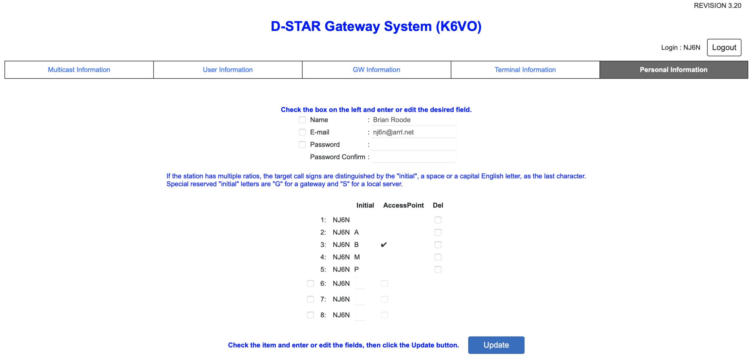
To use Terminal or AccessPoint mode, you must have a terminal entry which is comprised of your callsign followed by a letter designation in the eighth character position, e.g. “NJ6N^^^B” AND has the AccessPoint checkbox checked under the Personal Information menu on any G3 gateway system.
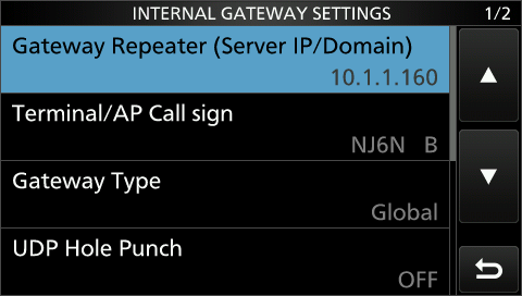
dv gateway – internal GAteway settings
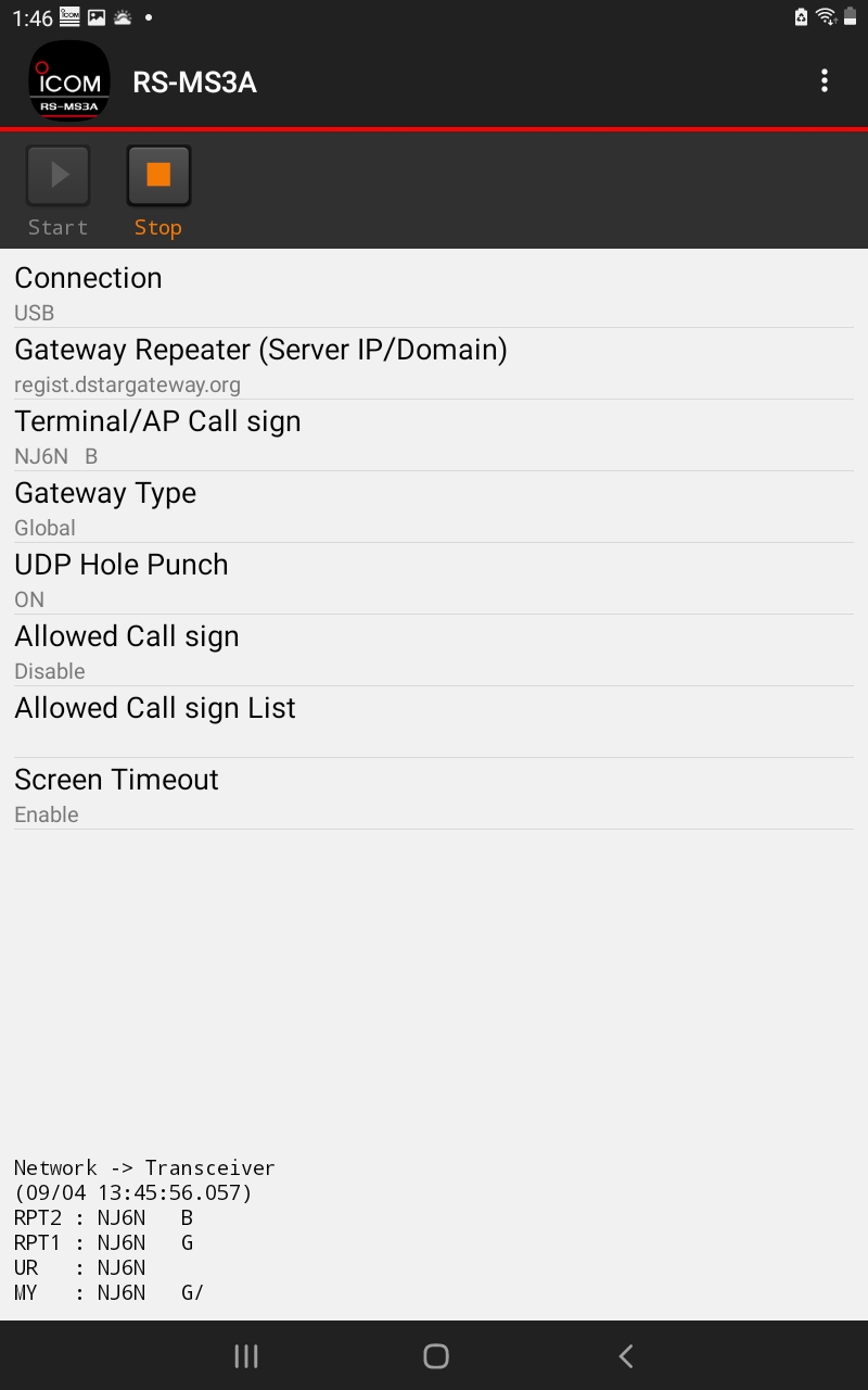
You must configure the built-in Internal Gateway in order to use Terminal or AccessPoint mode. You may alternatively use an external computer to do this using the RS-MS3A (Android) or RS-MS3W (Windows) application. The Internal Gateway configuration is identical to using these external applications.
Press Menu -> DV GW -> Internal Gateway Settings
Gateway Repeater (Server IP/Domain) is where you specify the system that will act as a directory server to translate a given callsign or zone repeater callsign into an IP address. You can enter any G3 gateway here, for example, regist.dstargateway.org. In the example below, I’m using the internal IP address of my D-STAR gateway that’s on the same network as my IC-9700.
Terminal/AP Callsign is where you enter your “Terminal” entry that has the ACCESSPOINT checkbox checked, e.g. “NJ6N^^^B”
Gateway Type is either Global or Japan
UDP Hole Punch – if you don’t want to configure your local router to forward port 40000 to your 9700 or 705, this supposedly makes it work anyway.
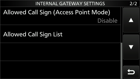
Allowed Call Sign (Access Point Mode) is where you can restrict accesspoint mode to specific call signs, or just leave it set to Disable
Allowed Call Sign List is the list of call signs you want to restrict access to.
Press Menu, then DV GW and then press the <<Terminal Mode>> menu item.
At this point you can use callsign routing, or zone routing.
Callsign routing routes your traffic to a specific user callsign, e.g. NJ6N. It locates the last known gateway that callsign was seen on by querying the Gateway Repeater.
Zone routing routes to a specific zone repeater, e.g. “K6VO^^^B”.
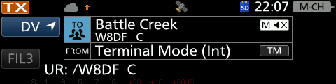
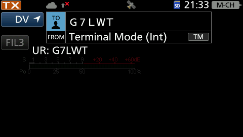
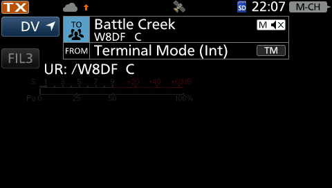
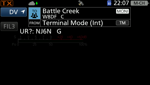
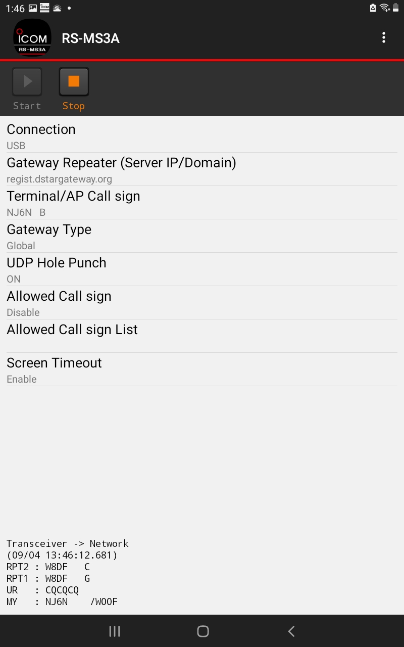
Pressing TO brings up a menu where you select the destination. First, select Gateway CQ, then you will be able to select a region, e.g. “USA Northeast” where you can select a remote gateway and module. (aka Zone Repeater). Selecting W8DF C from the menu enters “/W8DF C” into the TO Field. Icom has obscured the original display that showed the slash in front of the zone repeater call sign for clarity.
You may also enter a users callsign. This will route your traffic to the repeater where that callsign was last heard. Note: many repeater modules are linked full time to busy reflectors.
You will NOT be able to hear the traffic on the remote reflector unless you make use of the Remote Repeater Monitoring feature. Your transmissions will be transmitted through the connected reflector.
Note: If you see a red X next to a grey up-arrow when you transmit, it indicates an invalid or unknown “TO” call sign. Enter a different user or zone repeater call sign.
A valid call sign lookup is indicated by an Orange up-arrow when you transmit followed by a Green down-arrow indicating a response from the remote gateway.
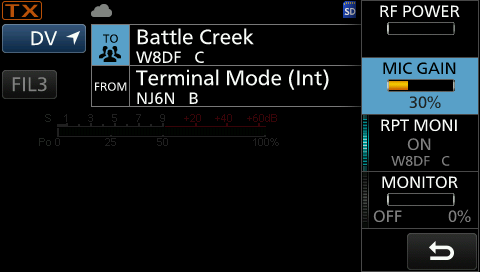
Remote Repeater Monitoring
On the newer radios, IC-9700 and IC-705, terminal mode allows you to connect to a remote G3 gateway and monitor as well as talk. Monitoring is accomplished through a connection the transceiver makes over the internet to dplus on the remote gateway.
You must first add a file called RptMoni.csv in the SDCard’s RptMoni folder.
Examples of this file are found on the Icom web site named RptMoni_sample.csv.
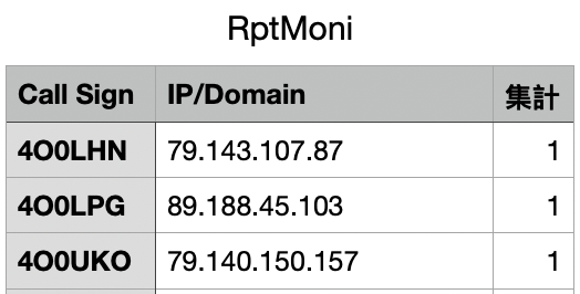
I believe the Japanese character in the third column header translates to “total” but I don’t know what that means in this context.
Press the Multi button, then press RPT MONI You should see ON displayed. Note: if you switch to a different gateway and/or module, the monitoring function follows so long as the IP address for the remote gateway is correct and the gateway is online and running dplus.
To use AccessPoint mode, Press Menu, then “DV GW” and then press the <<Access Point Mode>> menu instead of the <<Terminal Mode>> menu. You will now have a VFO display where you can configure the frequency you want to use with your second radio. The second radio should be set to the same simple frequency and DV mode.
When you are using AccessPoint mode, you will be disappointed to learn that you can not monitor the remote gateway over the RF link between the 9700 and your remote radio (e.g. ID-31, ID-51, etc.)
Terminal/Access Point Mode on ID-52A
Using the original ID-52 with an Android tablet also enables Terminal & Accesspoint modes. You cannot use Bluetooth – it looks like it should work, but the transceiver cannot talk to the tablet for some reason. Use an OTG USB cable between your HT’s microUSB port and the Tablet.
Download the RS-MS3A application from the Google Play store. You can also use RS-MS3W on windows, but RS-MS3I on the iPhone requires Bluetooth and that just doesn’t seem to work with the original ID-52A.
On the original Icom ID-52A/E, confirm SerialPort Function:
Set->Function->SerialPort Function to: CI-V (Echo Back OFF)
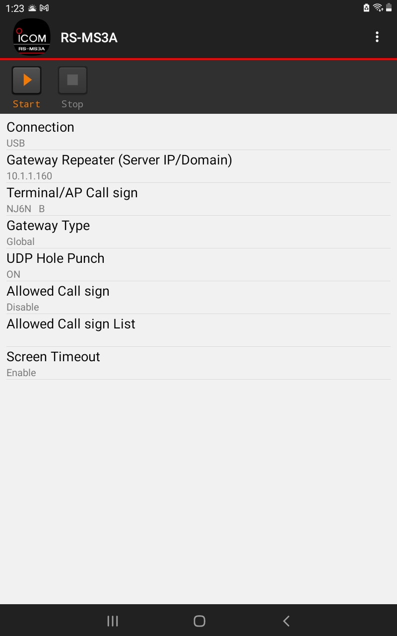
In the rs-ms3a application, configure the following
Set connection to USB
Gateway Repeater (Server IP/Domain) is set to a valid G3 gateway, e.g. rootg3.dstargateway.org, regist.dstargateway.org, etc.
Terminal/AP Callsign is your ACCESSPOINT Terminal callsign, e.g. “NJ6N^^^B”
Gateway Type: Global or Japan
UDP Hole Punch – Set to ON if you have not configured port forwarding to your tablet
Allowed Call sign – Enable for callsign control, or leave disabled
Allowed Call sign List is the list of call signs you want to restrict accesspoint mode to
Screen Timeout is either Enabled or Disabled
Press the Start (play) button on the RS-MS3A application to enable terminal mode. You should see a display with all of the pertinent callsign registers that changes when you press PTT on the radio to indicate where your call is being routed to.
Note: If you see the error message “Failed to Connect Network” when you transmit, that actually means the directory server failed to find an IP address for the ‘endpoint’ you entered. Try a different gateway or user call sign.
I would assume the newer ID-52A Plus and Anniversary editions would work the same, only they would work over Bluetooth.
NOTE: I believe Bluetooth Set ->Data Device Set->SerialPort Function should be set to CI-V(Echo Back OFF)
I believe the newer ID-52 radios support the “RptMoni” function provided you install the magic RptMoni.csv file in the RptMoni folder of the SDCard.
Note: I believe a lot of things, your mileage may vary.
G3 Database Query NoteS
When you press PTT, A query is made on the directory server to find the IP address of the endpoint you entered (User or Zone Call sign). Here are the queries made:
select target_cs from sync_mng where target_cs=’NJ6N B’ and pc_hostname=’ACCESSPOINT’ and del_flg=false limit 1
select dbupdate_allow_flg from unsync_gip where zonerp_cs=’K6VO ‘
select allow_flg, zonerp_cs from unsync_gip where zonerp_cs=’NJ6N ‘
select timestamp(0) ‘now’
select zonerp_ipaddr from sync_gip where zonerp_cs =’NJ6N ‘
update unsync_mng set mod_date=’now’ ,receive_time=’2025-09-04 21:45:10′ where target_cs=’NJ6N ‘
select * from sync_mng where target_cs =’NJ6N ‘ and last_mod_time >= ‘EPOCH’ and reg_date >= ‘EPOCH’
select * from sync_mng where target_cs =’NJ6N ‘ and (last_mod_time+’1 days’) < (select receive_time from unsync_mng where target_cs=’NJ6N ‘)
select sm.zonerp_cs, sm.arearp_cs, sm.pc_ipaddr, usm.blacklist_flg from sync_mng sm,unsync_mng usm where sm.target_cs=’G7LWT ‘ and sm.target_cs=usm.target_cs and sm.del_flg=false
select zonerp_ipaddr from sync_gip where del_flg=false and zonerp_cs=’G7LWT ‘
Leave a Reply