I have been using Motorola CDM-750/1250/1550 radios to build digital and analog repeaters, full duplex links, and digital hotspots for some time. Quite a few of the radios I have do not have a front panel display. However, they do have a 16 pin accessory jack that has all of the usual signals including TX/RX Audio, PTT, COR, etc. They also provide a Receive Signal Strength Indicator (RSSI) line that can be used to drive an S-Meter.
Looking around to see what others have done to add S meters to these radios, I found several examples of adding S-meters to different /\/\otorola radios using operational amplifier circuits. I also found an article about building an LED bar graph with Arduino.
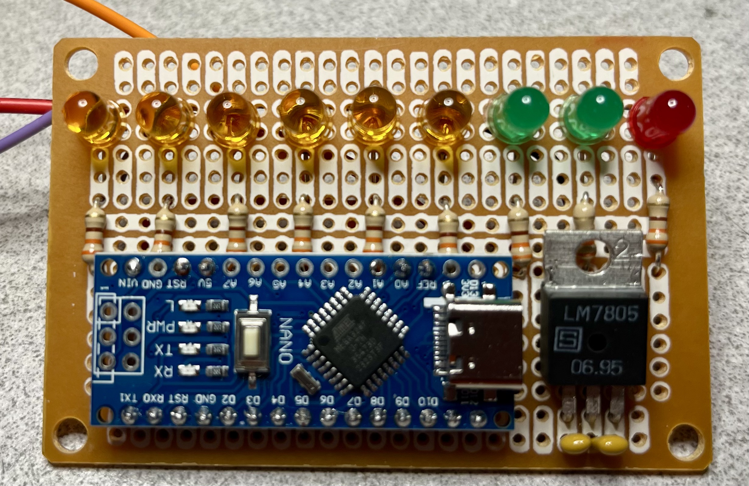
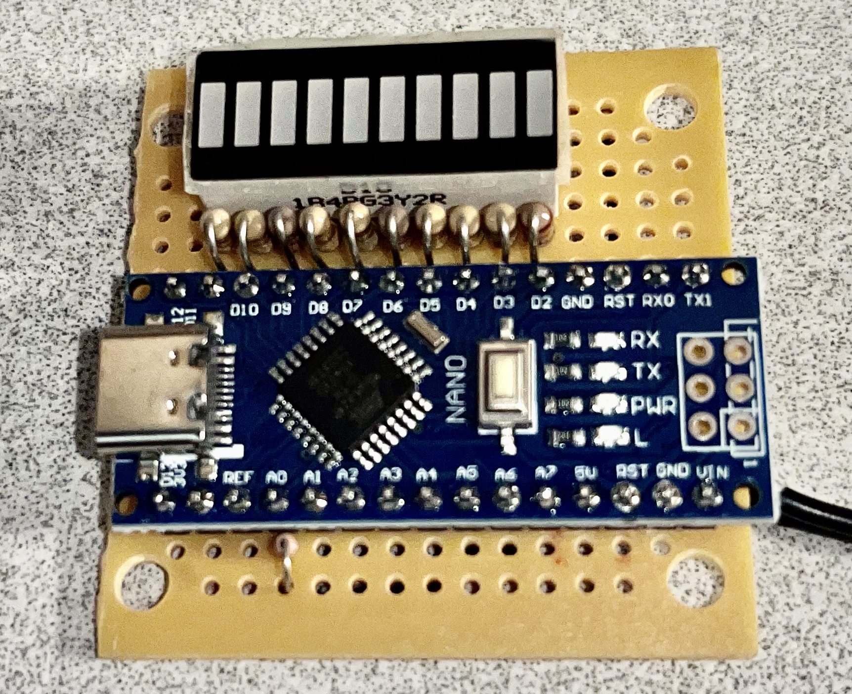
An analog input is used to drive 1-10 LEDs using the “map” function. I only had room for 9 LEDs on my prototype board. I determined the low and high values provided by the RSSI signal pin on the radio, and configured the map function accordingly.
After adding a 7805 5V voltage regulator, I managed to put that right in front of the USB C programming connector on the Nano. Oops! To mitigate that mistake, I added RX/TX/GND header pins so that I could program it with an external USB to TTL adapter. I may design a PCB for this and move things around to be more logical.
The amber LEDs turned out to be very directional and harder to see off-angle. If I make another one of these, I’ll use better LEDs more like the green and red ones I used.
For testing, I used a CDM-1250 that has an S-Meter so that I could compare the readings. Using the service monitor to make more official readings is the next step.
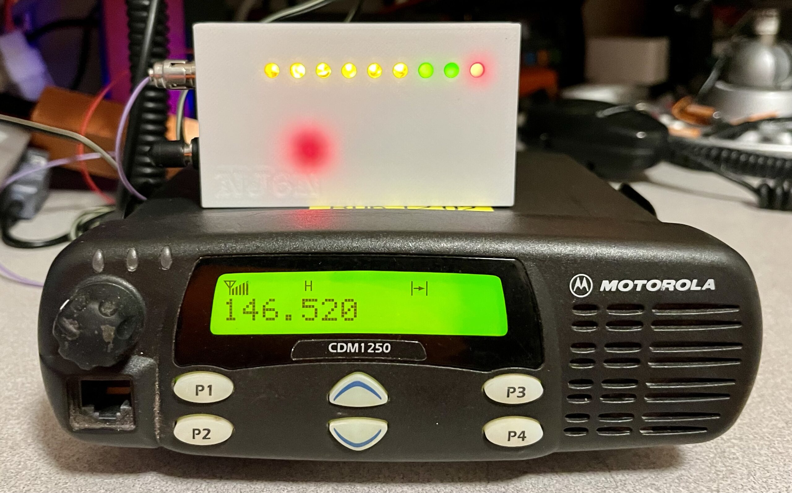

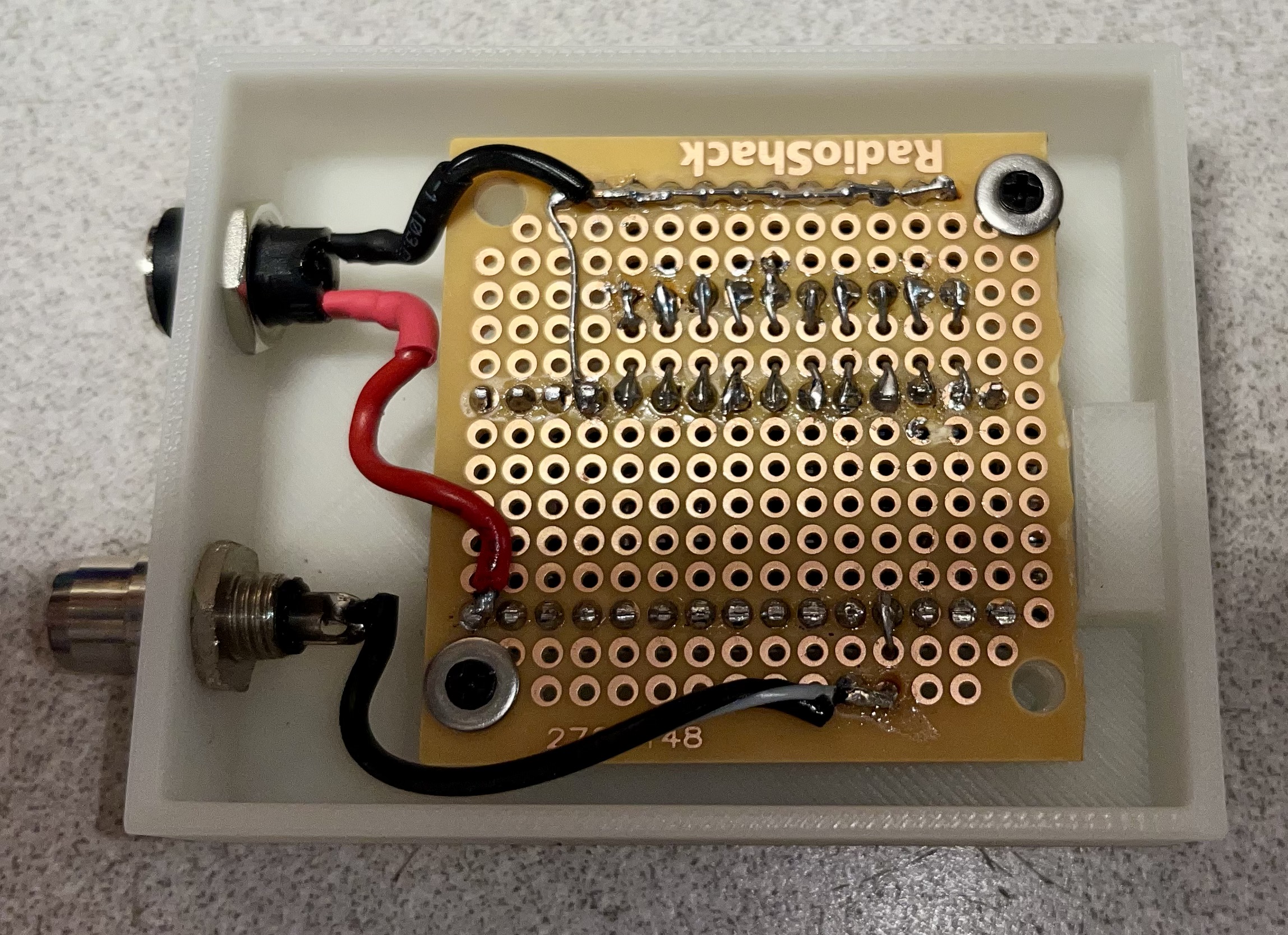
I designed a simple enclosure for the circuit and added a coaxial power connector for 12 volts and RCA jack for the RSSI input.
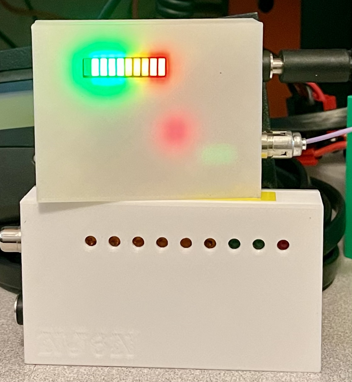
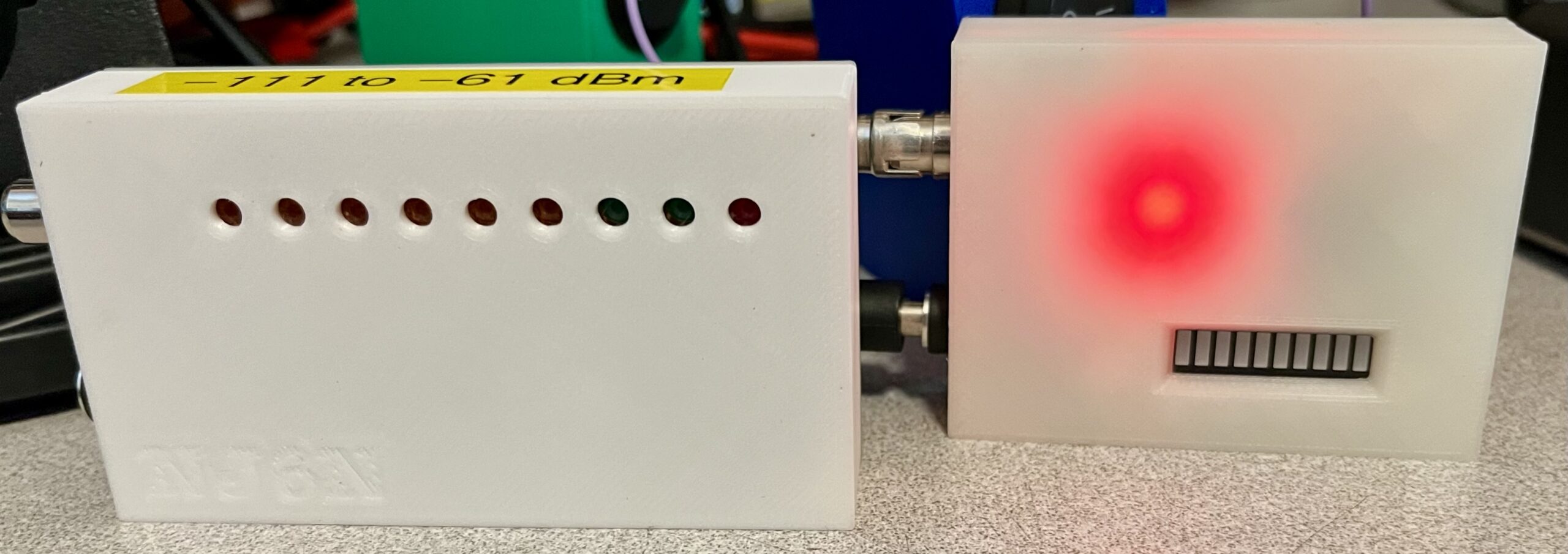
Version 2 is a little smaller and easier to construct using a LED module. I didn’t get to pick the colors however, so they don’t quite make sense.
Leave a Reply