I have used an APO-3 automatic power off unit in my vehicles for many years. I recently needed to add a second one for my rear-facing dash camera in my truck and wondered what it would take to design and build one myself.
I decided to use an Arduino Nano as the microcontroller since I had a bunch of those already. The first question was, how do you measure 12-15 Volts with a 10bit 0-5V ADC? A voltage divider is the answer! I found this article very helpful in figuring out how to do this.
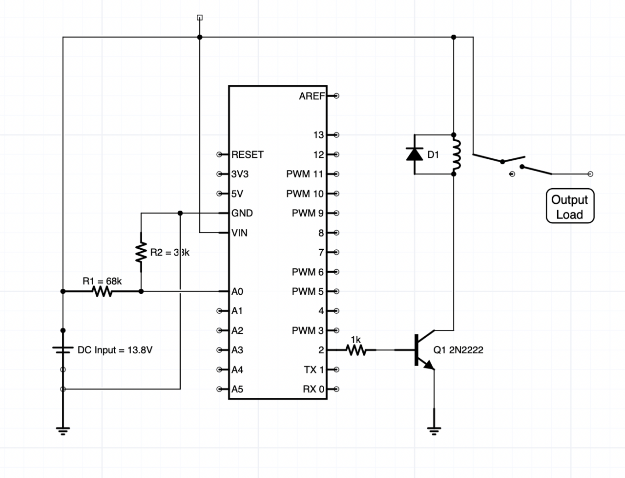
I set up a voltage divider between the DC input and ground using a voltage divider comprised of a 68K and a 33K ohm resistor.
I was surprised to learn that the Arduino boards have on-board voltage regulators. The power source can be 5-20 volts as long as you keep the current consumption very low. This means you can’t run a relay directly from an I/O pin, but you can drive a transistor without any problems.
Here’s the crude schematic I created using iCircuit

I used a 2N2222 NPN transistor to drive a 12VDC relay. A 1N4148 diode provides protection from inductive flyback from the relay coil.
Once I had the hardware, I needed to write an Arduino sketch to do the work. I set up a loop that measures the voltage and controls a high current relay.
When the voltage goes above 13.00 volts, i.e. when the engine is running, the relay is engaged. The voltage in a vehicle increases from 12.6 or so to 13.5+ volts when the engine is running and charging the battery. I’m not sure how this works in a Tesla, but for old fashioned internal combustion engine vehicles, this is fairly standard.
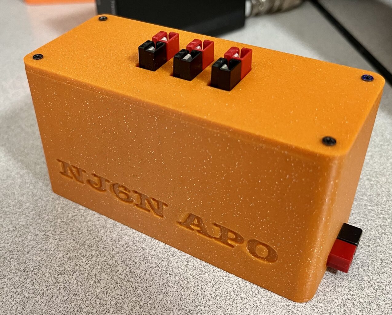
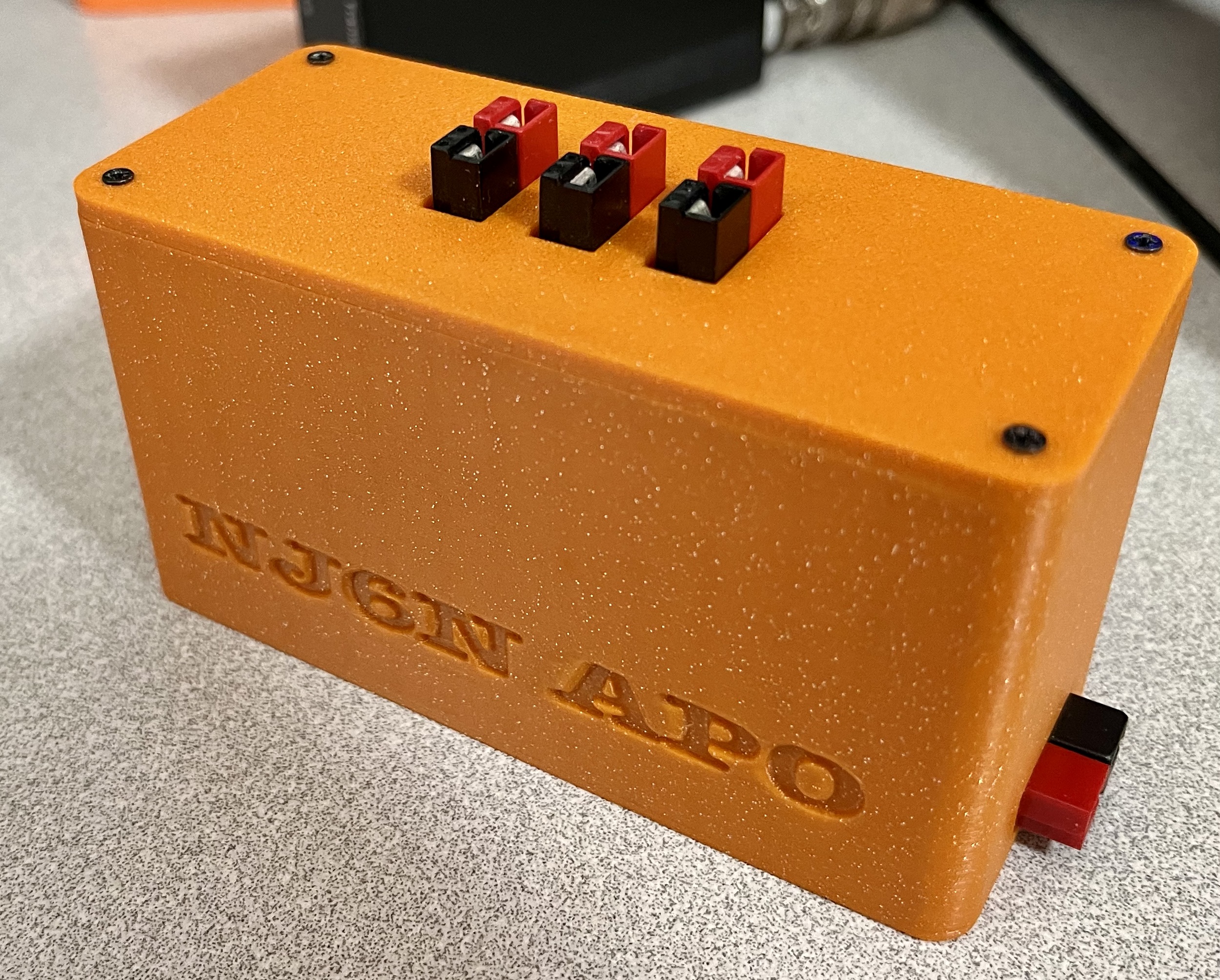
The relay is connected to three Anderson PowerPole connectors to provide power to multiple devices.
Once I had my basic design functioning, I tested it using a 50 watt mobile radio. And of course some very tricky problems emerged. Claude, W6CAG had warned me about one of them. When you have a single set point, say 13V at which the relay engages at or above, and disengages below, any voltage variation near that set point can cause unwanted rapid switching of the relay. A Schmitt trigger is often used to mitigate this issue by adding hysteresis.
So I added a low set point at which the countdown timer will start the counter to shutting off the relay. If the voltage drops below the low set point voltage, ~12.6 volts, a delay counter is triggered to count down 300 seconds (or however long you want it to be). A one second delay in the loop provides the clocking. Once the counter reaches zero, the relay is disengaged.
However, there’s still a problem. When you’re transmitting with a 50 watt radio, the current draw is about 10 Amperes. That causes enough of a voltage drop to trigger the power off timer. One solution would be to monitor the actual battery voltage, at the battery. That would require an additional sense line directly connected to the car battery. That goes against the design specification of having a self-contained automatic power control box. If I have to run another wire directly to the battery, I might as well run a wire to an ignition on source to determine when the ignition is on and use a simple relay circuit for my radios.
Interestingly the commercial APO3 device I had bought years ago has the single set point issue. If I set my bench supply for precisely 13 Volts, the relay would activate. The current draw from the relay alone caused the voltage to drop below 13 Volts, and the countdown began! Once the timer expired, the relay is turned off and the voltage rises to 13V and the cycle repeats. I believe the firmware was modified to add hysteresis in newer versions of the APO3 device.
For now I’m okay with the countdown timer being long enough to maintain power during my transmissions. When I’m no longer transmitting and the vehicle is shut down, the countdown timer will shut off the relay and ensure the attached radio won’t deplete my starting battery.
I designed a case that houses the Arduino Nano board and relay and allows access to the USB C connector for (re)programming.


The key feature of the APO device is that you don’t have to wire a relay directly to your ignition in order to have the same functionality. Plus you get the bonus of a delay before the attached device loses power. That’s really handy for example when refueling. Your radio remains powered up for whatever delay you set and goes off so you don’t have to remember to turn it off. Standby current is about 17 mA.

Leave a Reply