Our high-level 440 and 220 repeaters on Santiago peak use modular rack-mounted Tait radios. Our 440 band repeater uses a T855-20 series 1 module for receive and a T856-20 module for transmit. The transmitter is capable of 25 watts or better, but we have configured it for 10 watts output to drive an external TPL (or TE Systems) 100 Watt amplifier.
Our 220 machine uses 300 series modules. A Tait T375-42 is used for receive and a T377/Ex-16 for the exciter. A T377-32 Power Amplifier produces about 50 watts.
Earlier this year, our 440 repeater developed an issue where it would stop transmitting during our weekly nets after about 30 minutes of use. We theorized that the power amplifier was likely the culprit given it has the most high current heat producing job in the system.
A backup amplifier was bench-tested for 40 minutes at full output power.
Joe, WB6HRO and I went up to the site to check it out. When we got up to the repeater site, we were immediately greeted with the very high temperature inside the building. It turns out the air conditioning had failed and we found out later that repairs would end up taking a couple of months. It turns out that the start of that air conditioning problem coincided with the start of our issues.
We replaced the 100 watt amplifier just in case it was also having problems.
A few weeks later the air conditioning was repaired and our issue went away. I started wondering how the power control and thermal cutoff circuits worked in the Tait transmitter. To find out, I purchased an identical (but non-working) T855-20 transmitter module on Ebay.
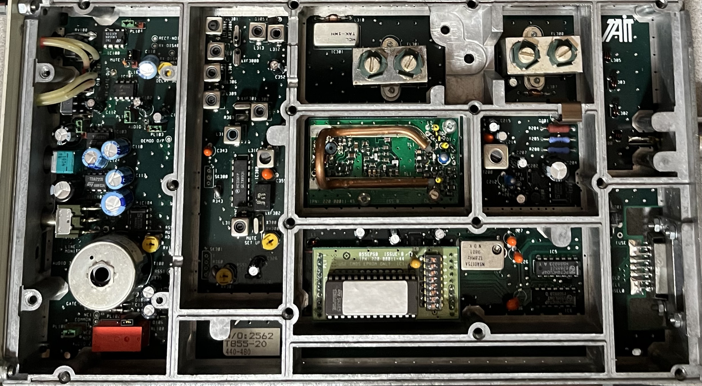
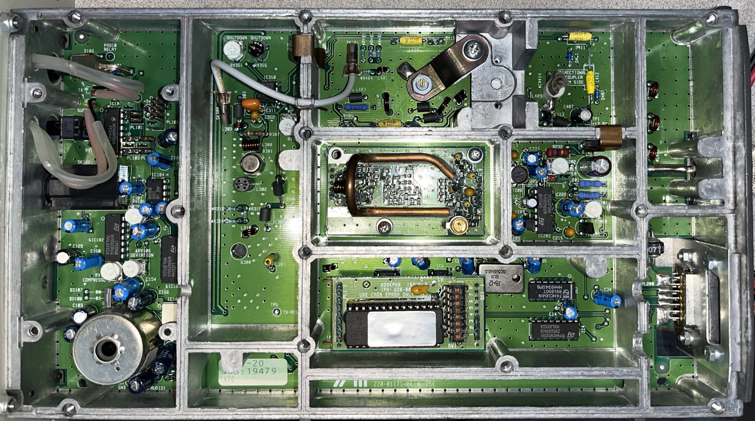
Tait radio modules are very well designed for learning more about how a synthesized PLL driven transmitter works. Each stage has its own compartment.
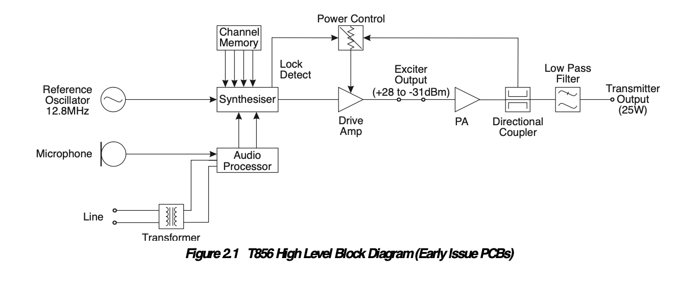
A full service manual was available for this transmitter that matched the part numbers on the PCB inside the unit. That was super helpful. Here is the high level block diagram:
Following the troubleshooting steps from the service manual, I started with the local oscillator / VCO circuit. I loosely coupled a frequency counter near the VCO to determine if the frequency, based on the label on the outside of the unit, made sense, and it didn’t. Measuring the VCO steering voltage, it was clear that the synthesizer was not working.
One of the fault isolation steps is to insert a known good EPROM and then determine if the Synthesizer and Phased-Lock Loop is working correctly.
Now I had to figure out how to read and write 27C64 EPROMs again. My last EPROM programmer used an ISA bus card in my IBM PC XT in the 80’s. Back then, just about everything had an EPROM in it. I looked around for a modern EPROM programmer and found the XGecu T48 on Amazon.
I didn’t have a known good EPROM so I decided to read the current EPROM to see what was in there. It was all FF’s which means it was entirely blank! I suspect the company that sold this unit as scrap erased the EPROM per company policy.
The T856-20 is designed to be use with either 6.25KHz or 12.5KHz channel spacing. Here in Southern California, we use 20 KHz spacing on the 440 band. This meant that the software provided by TAIT to program the EPROM which set the divider values for the synthesizer would not work.
At first, I used the PGM800 program to create the data for the EPROM using 12.5KHz steps. After burning that ERPOM, inserting it in the radio, and adjusting the VCO steering voltage to 10V, the transmitter came alive!
I was able to get the radio programmed to 447.175 MHz which is 5 KHz too low but it worked!
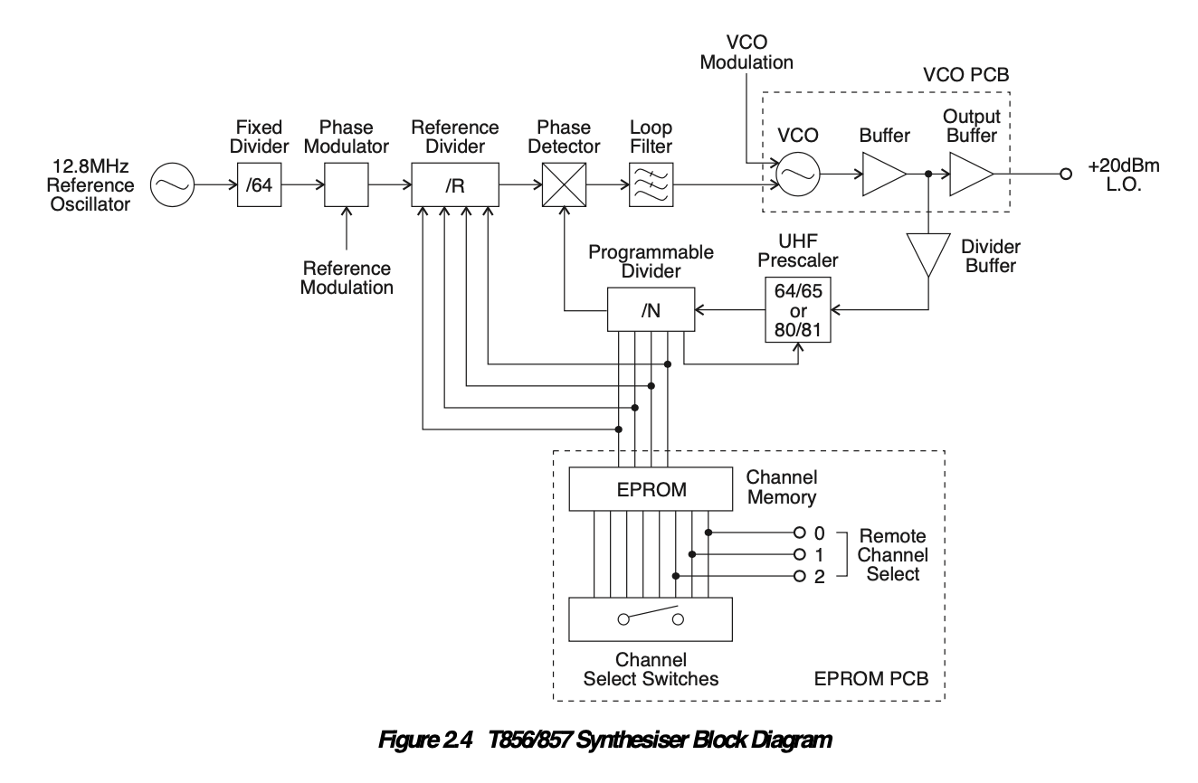
Here’s the block diagram of the synthesizer / PLL circuit that produces the local oscillator:
I was able to find a couple of really helpful references about programming the EPROM for the NJ8820 synthesizer on the Internet. John, VK5DJ wrote an application that calculates the necessary data map for the NJ8820 synthesizer used in the PLL. It allows you to specify the channel spacing, etc. His program is based off of work done by David, GD4HOZ who describes how to program an Simoco FX5000 base station that uses the same synthesizer IC.
Once I had the right data using 10 KHz channel spacing, I erased and eagerly programmed a 27C64 EPROM.
Everything worked as expected, and now my transmitter was on 447.180 MHz. I then followed the alignment procedures.
During the alignment, you normally adjust the output power to 25 watts. After that, using the voltage you measure while the PA transistor is cool, you calculate a voltage for the high temperature cutoff and adjust the power output during simulated cutoff (shorting a test point to ground) to 5 watts. If you later adjust the output power to only 10 watts, the power achieved during thermal shutdown is nearly zero! This is why our transmitter quit transmitting entirely.
I adjusted the power on my transmitter to 10 Watts, and adjusted the power output during thermal cutoff to 1 watt.
If you want to learn more about repeaters in general, Tait offers some excellent online reference material.
Leave a Reply