I have always enjoyed the 1.25M band for FM. Recently I was going through my old radios and found two Alinco DR-235 mobile radios. One works great now that I replaced the mic cord. The other one is one that I bought on ebay as a “tech special” It has quite a few problems and I’m not sure I’ll be able to get it working again.
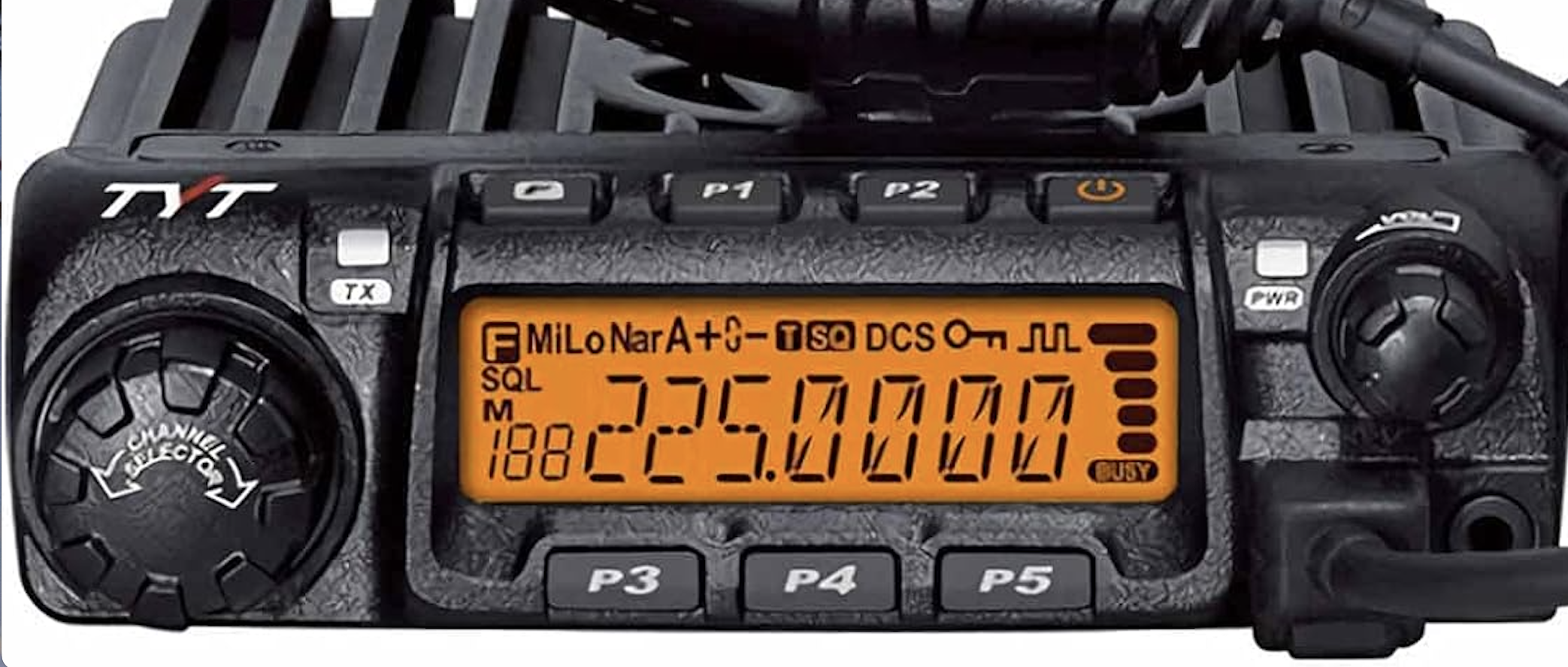
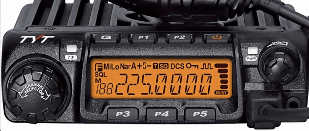
There is a cheaper version of this radio sold by TYT called the “TH-9000D Plus” for 222 MHz. I was curious how close it was to the DR-235 so I bought one. It turns out that it’s very close! It has the exact same display and seems to be made from the same components. The firmware is different and it has different controls. For example, instead of buttons labeled with their function, it has “P1-P5” While I can guess that you can reassign the buttons perhaps, I would rather have clearly labelled buttons for commonly used functions. At any rate, the radio works well once you figure it out.
One thing that I found interesting was that while the display is exactly the same as the Alinco DR235, on the Alinco the “A” indicator is to indicate AM receive mode, while on the TYT-TH9000 it means “Auto Power Off.” There is apparently no AM reception on the TYT radio.
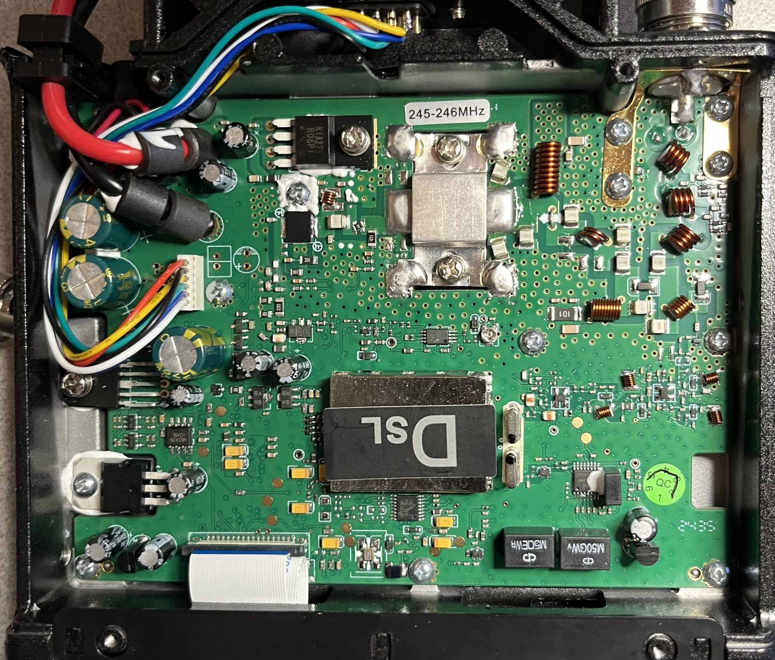
As with Alinco radios, there is a JST ZH socket on the circuit board and 9 pin D-Sub cutout with 2.5mm threaded holes on the back panel to facilitate interfacing to the radio. The connectors are not included with the TYT radio, however. The signals provided include TX audio, RX audio, COR (RX indication), PTT, and +5V power. These are all of the signals that you would need to create a repeater, EchoLink (SVXlink)/Allstar node, or digital hotspot.
First, you have to find the right connector. After some web research, I found a JST ZH 1.5MM 6 Pin female connector that works with the socket in the radio on Amazon. They are also available from Mouser and Digikey. You can also find pre-made cables from sellers on ebay for building hotspots and repeaters.
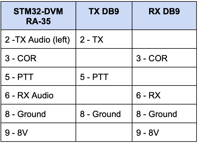
Here are the pinouts using the JST ZH pigtail cables from Amazon:

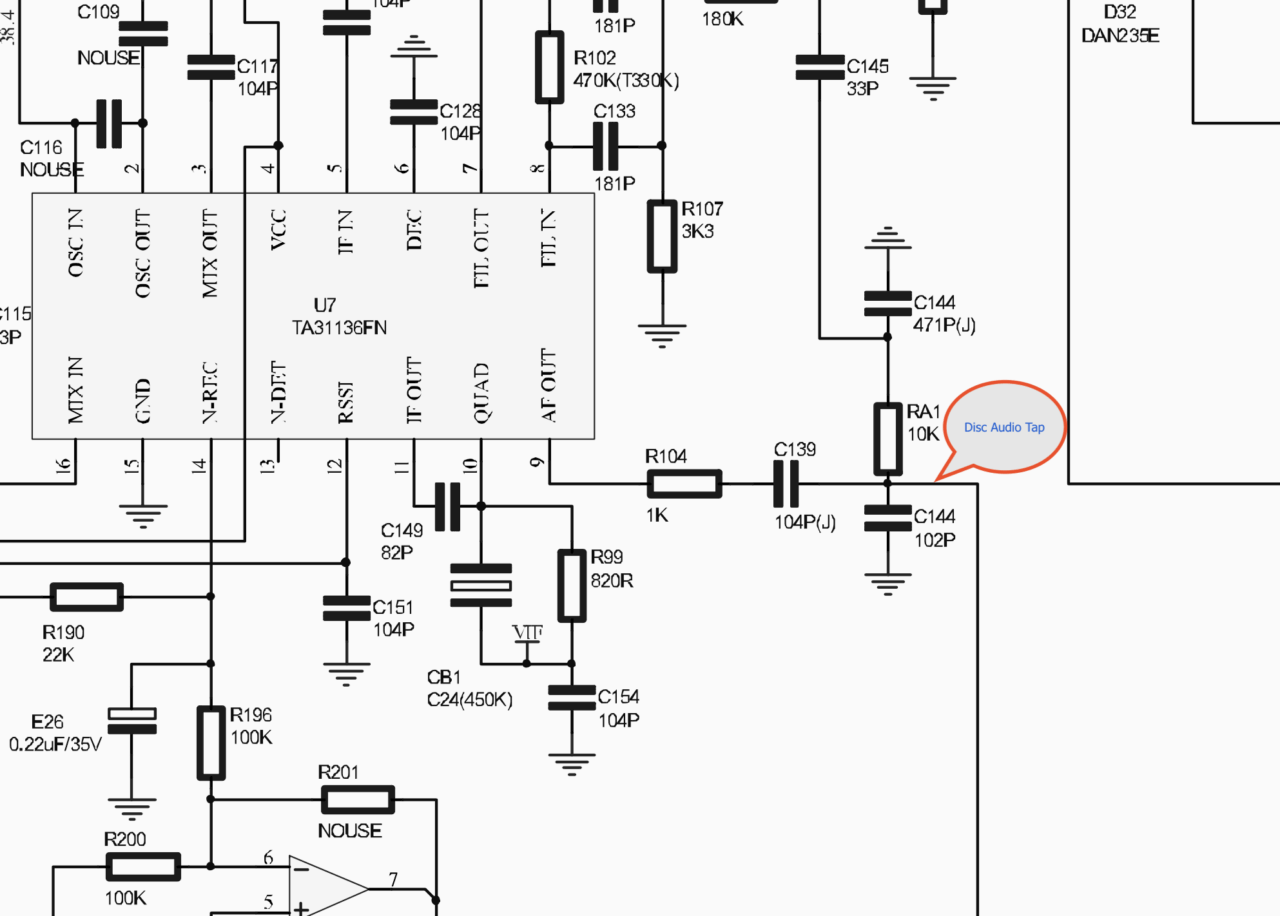
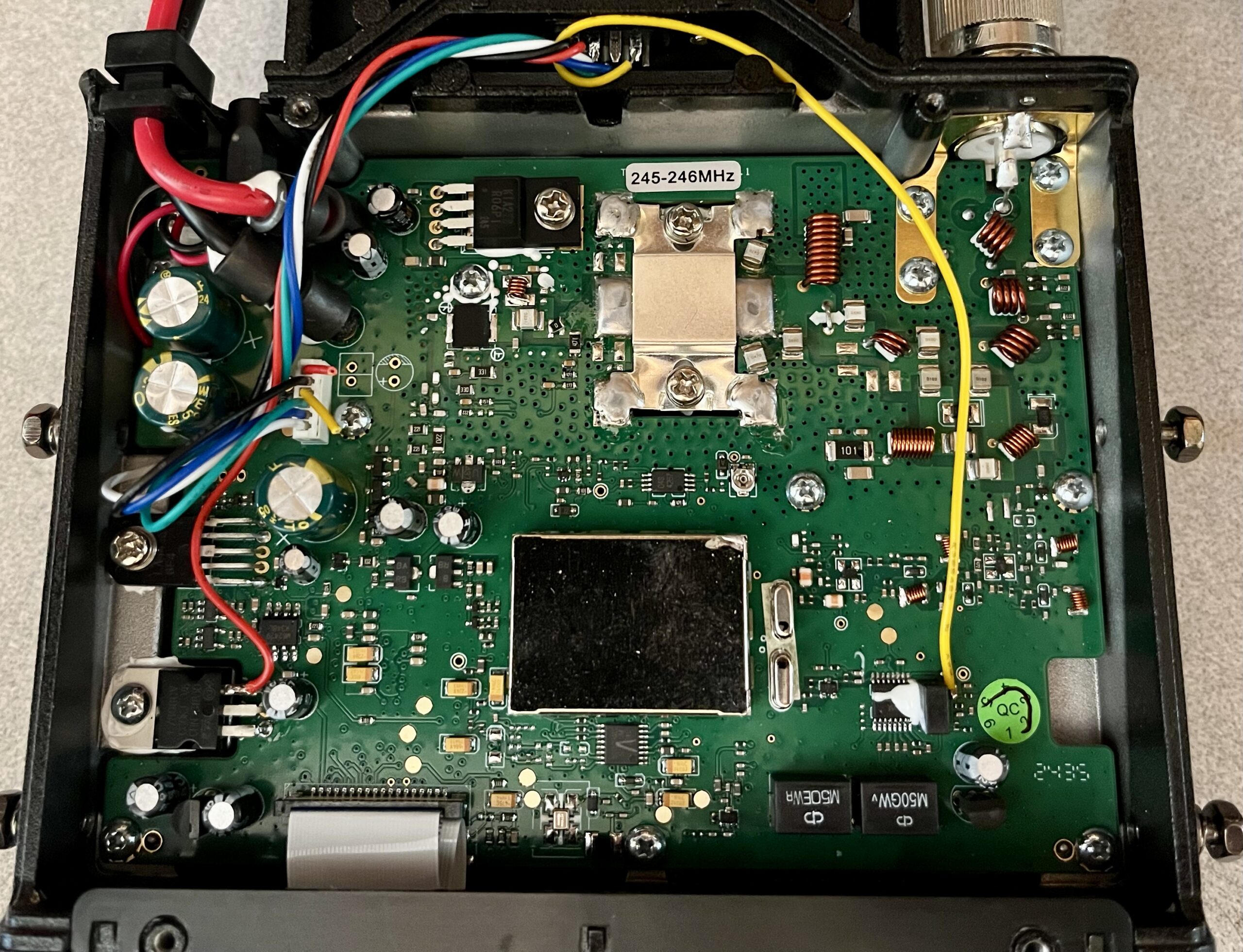
The Receive Audio signal is de-emphasized and the level is controlled by the volume control. Discriminator audio works best for digital hot spots and for interfacing to a repeater controller if you’re building an FM repeater. I found discriminator audio on pin 9 of the 31136 FM detector/second IF integrated circuit and tapped into the signal after a series resistor and surface mounted bypass capacitor.
I wired the DC output on Pin 9 of the S-Sub connector to the output of the 8V voltage regulator to power my Pi-Star RPi computer & MMDVM modem. Power to the 8V voltage regulator is controlled by the CPU so it turns off when you turn the radio off.
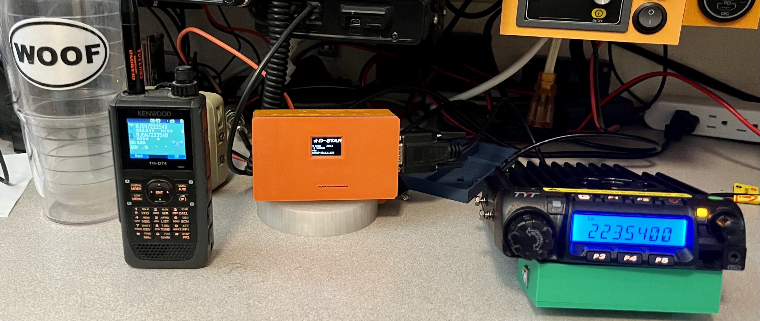
Many of us have the Kenwood TH-D74 tri-band 2m/1.25m/70cm Handie-Talkie with D-STAR capability. I thought it would be interesting to build a digital hotspot on the 222 MHz band.
Having built a lot of multimode hotspots and a multimode repeater using STM32 based MMDVM boards and mobile radios, building a 222 version shouldn’t be too difficult.
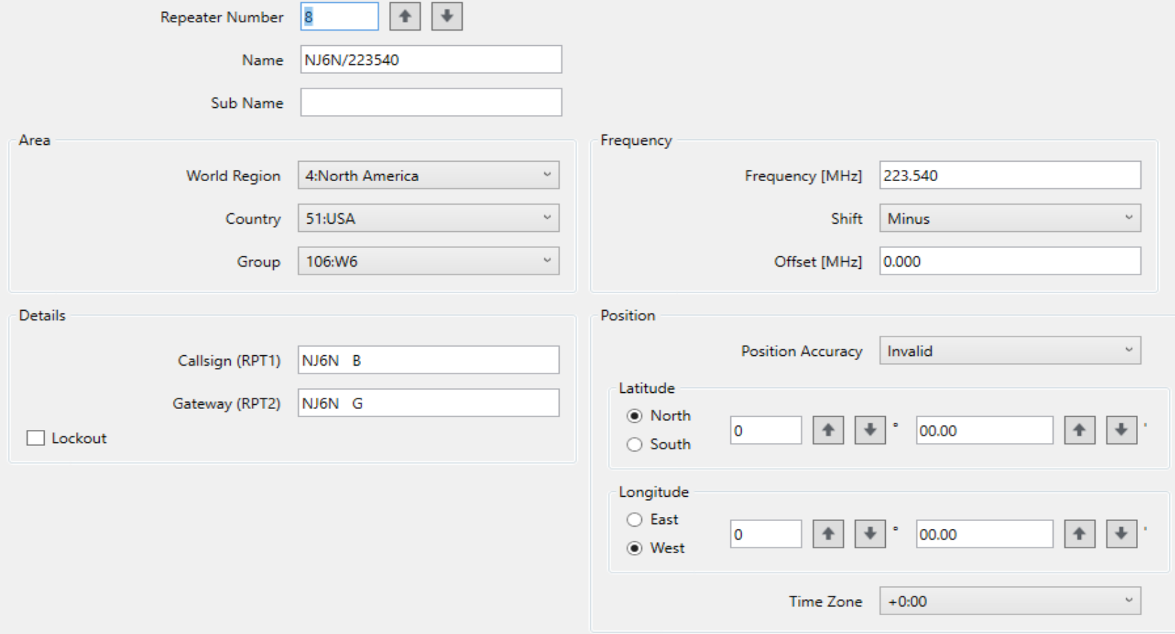
The pin configuration I used for the DB9 connector interfaces directly with the STM32-DVM MMDVM modems that I built previously. Once connected, I adjusted the receive audio level and immediately ran into problems getting it to work with my Kenwood TH-D74. I configured a “DR” entry for simplex operation in the Repeater List.
Note: I chose to use module “B” for the module designation. There’s hardly any 222 MHz activity on D-STAR so there isn’t any convention for this yet.
Pi-Star requires radios to transmit using the D-STAR gateway protocol and to accomplish that, you enter a repeater offset either plus or minus with an offset of 0.00 KHz. That allows you to use a simplex frequency while forcing the radio to use the gateway protocol.
Here are screen shots of the two different configurations. Memory channel worked, but Repeater List did not. Let me know if you know why.
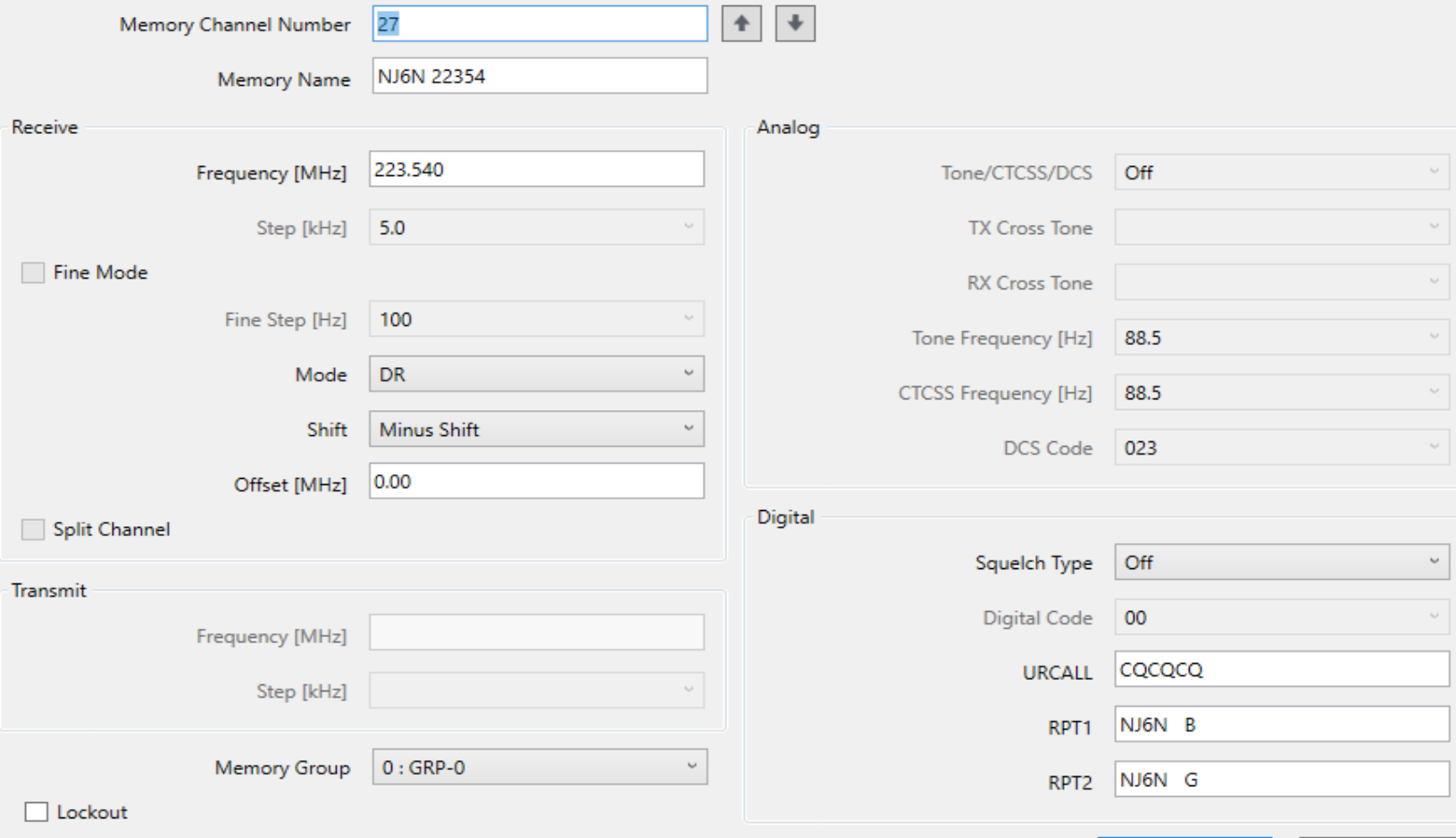
Using the Repeater List entry, the Pi-Star node could see my transmissions but they were not being sent out to the remote reflector that I was connected to. I could receive reflector traffic fine and my SDR could hear my D74 transmissions.
After fiddling for a while with various settings, I was able to make it work by configuring a regular memory channel in the D74 configured for “DR” mode with a zero offset as described above. That worked and I was able to talk on the D-STAR reflectors.
To make this into a repeater, I’ll need a second radio to allow for duplex receive and transmit at the same time. I already have a 222 MHz duplexer for this and a Comet CX-333 144/220/440 antenna on the roof.
Building a Repeater
Building on the success of my 222 MHz band digital hotspot, I bought a second TH9000 222 MHz transceiver so that I could build a full duplex repeater.
I added the interface cable and DB9F connector to the rear panel of the radio. This time I drilled and tapped the DB9 connector screws with 4-40 threads to accept standard DB connector spacers. I did not tap discriminator audio since this would be the transmitter for the repeater.
There is something to be said about making them the same so that they could be swapped in the event of a transmitter PA failure for example.
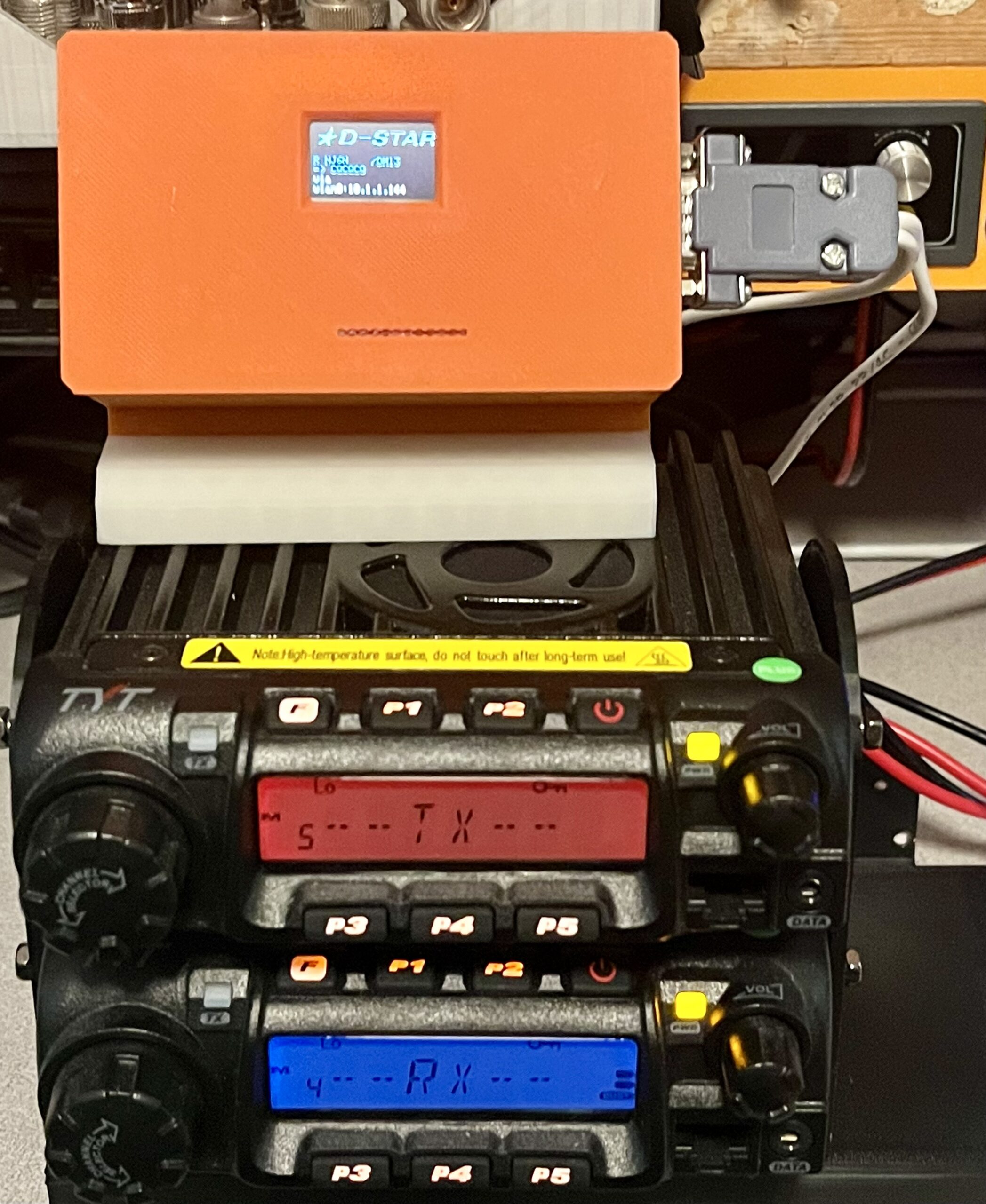
I fabricated a cable that routes the signals from the two transceivers to either a STM32-DVM MMDVM modem for Digital modes or Masters Communications RA-35 SVXLink interface for FM/EchoLink.
With the two transceivers, one for RX and one for TX, interfaced to the MMDVM modem, I now have a full-duplex repeater for FM & Digital Modes.
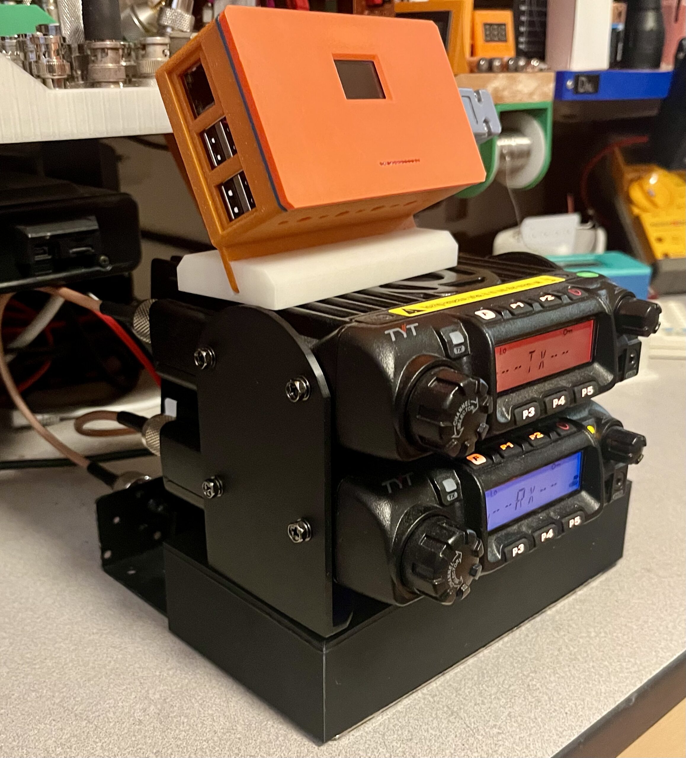
I designed a mounting bracket for the two radios to keep the installation tidy. The transmitter is mounted on top. I also designed a fan bracket for the transmitter. If I run this repeater at 50 watts, it will need additional mechanical cooling.
73, Brian NJ6N
Leave a Reply