Recently, someone mentioned they were looking for a code practice keyer during one of our HF nets. I have a few older keyers in my collection including a CMOS keyer that I built from a QST article back in the early 80’s or so and a Logikey K-1.
I had recently built a very simplistic code practice oscillator using an Arduino Nano and wondered if anyone had built a full featured iambic keyer using Arduino.
It turns out that Anthony (Goody) Good, K3NG has an outstanding open source keyer project that provides more features than one could ever imagine. Features include adjustable speed up to 999 words per minute, up to six selectable transmitter keying lines, PS/2 (or USB) keyboard support, WinKey emulation/contest logging, Optional LCD or OLED display, macro memories, Iambic keying, Beacon/Fox mode, and a CW decoder just to name a few!
The basic keyer will run on an Arduino Nano, but you will need an Arduino Mega to implement the more resource intensive features.
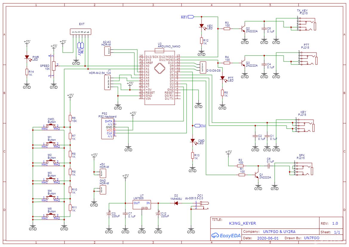
Here is the basic schematic:
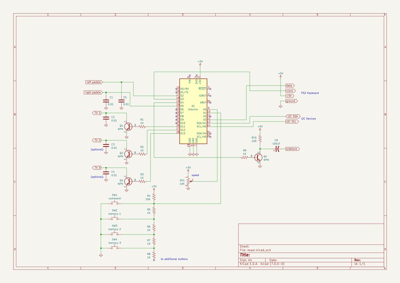
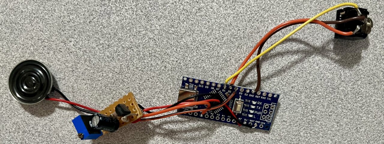
I wired up an Arduino Nano with a NPN transistor to drive a speaker and inputs for the keyer paddle and I was in business with a simple keyer! I added a potentiometer for speed adjustment but found out later that you could also enter command mode and send “W” in CW to adjust the speed.
I could see the potential in this keyer so I looked to see if anyone had designed a circuit board for this project. It turns out that there were quite a few out there. UY2RA & UN7FGO had designed and uploaded their Gerber files to PCBWay. There are multiple ways to build the project with one or two circuit boards. One board has everything on one PCB and another uses the same main PCB but provides a second circuit board for the front panel controls. I went with the basic single PCB design and ordered 5 of them for $5 plus $19 shipping!
The best (and probably safest) place to download the Arduino code for this project is from Github. The Wiki section is the best place to get started.
K3NG has an excellent YouTube Video to get you started with how to configure, compile, and install the necessary Arduino code. Take your time, the configuration options and settings are somewhat complicated and there are a LOT of them!
I designed several cases for this project. I really like how my version 2 case came out.

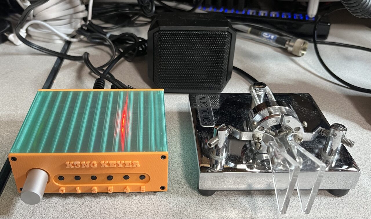
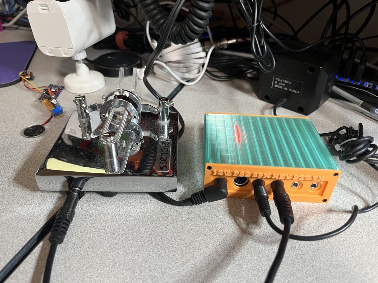
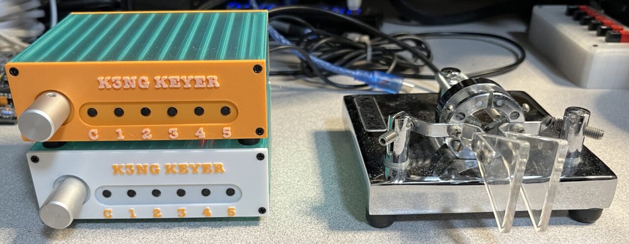
The circuit board slides into a slot in the main body of the case and the front and rear panels lock it in place. If you’d like to build one, I have uploaded my STL files to Thingiverse.
Here’s a quick test of the latest keyer I’ve built.
The schematic for the PCB has a few additional features.
I am still learning about this fantastic keyer and what it can do.
Vy 73,
Brian
NJ6N
Leave a Reply