Way back in April of 2023 I bought a QDX digital transceiver from QRP Labs. QRX stands for “Qrp-Labs Digital Xcvr”. I thought it would be fun to take with me on trips. I finally got around to building it in August, 2024.
The instructions are very good with excellent diagrams and illustrations on how to wind the toroids, how to install the PA transistors, etc. It’s super important to use the instructions that pertain to the version you purchased, especially if time has passed since you bought it. Improvements seem to be made continually.
Things to pay special attention to are indicated in red throughout the manual.
You have to take your time and be careful to verify every part is installed properly in the correct location. Resistance checks are used to verify placement of toroids and that there aren’t any short circuits caused by nicked enamel, etc.
It’s a good idea to read through the build instructions completely before starting so that you know what you’re getting yourself into. You can cross out sections that don’t pertain to your model of unit.
Winding the standard toroids is easy. Using the length of wire indicated and starting in the right position, you simply wind the correct number of turns.
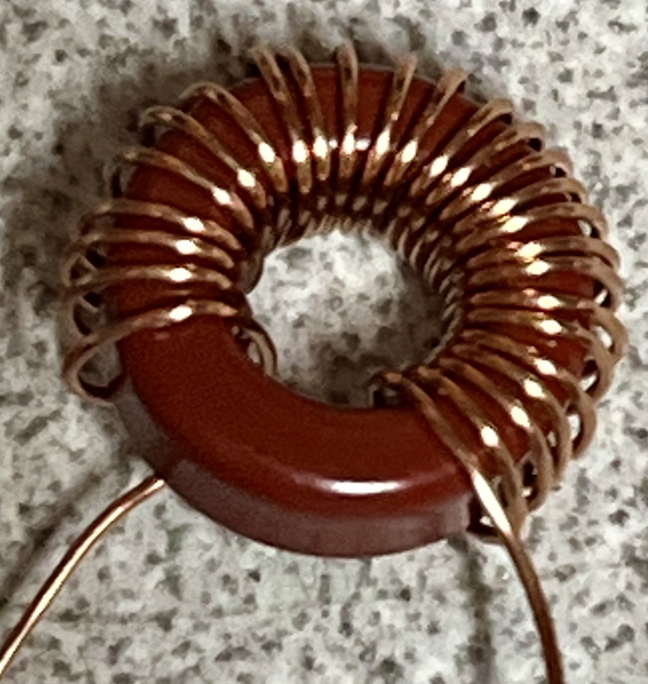
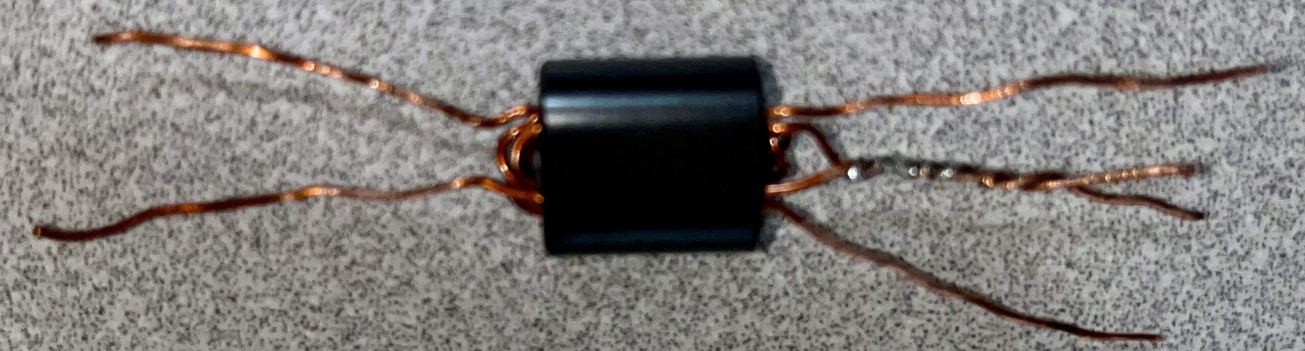
Winding the transformers are a little more tricky. There is a separate manual for winding the first toroidal transformer (T1) on a binocular core. You have to decide how to wind it based on what voltage you are going to power the kit with, and which technique you want to use. I chose the “Really Weird Twisted Sisters Transformer” technique with a 3:2 ratio for operation on 12 volts. This technique solves a parasitic resonance problem and improves performance on both low-band and high-band versions of the QDX. Mine came out pretty ugly, but in the end, it worked as designed.
There is also a tapped toroid which requires you to create loops of wire at designation number of turns to create taps.

I had never wound one like that before but it wasn’t too hard.
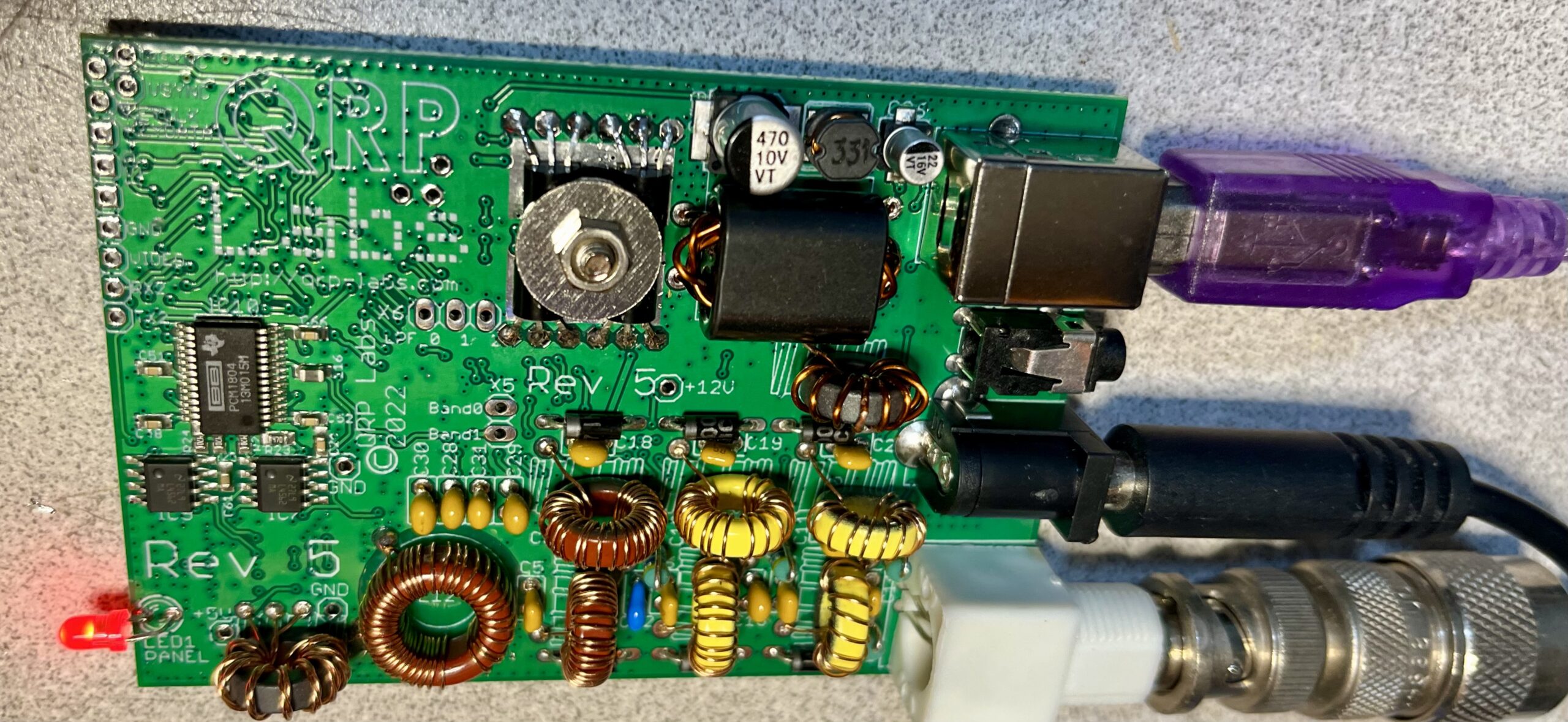
Once I had everything built, I closely examined the board for any issues. I did find one solder bridge. It was in a place where the two traces are super close together so you have to be really careful!
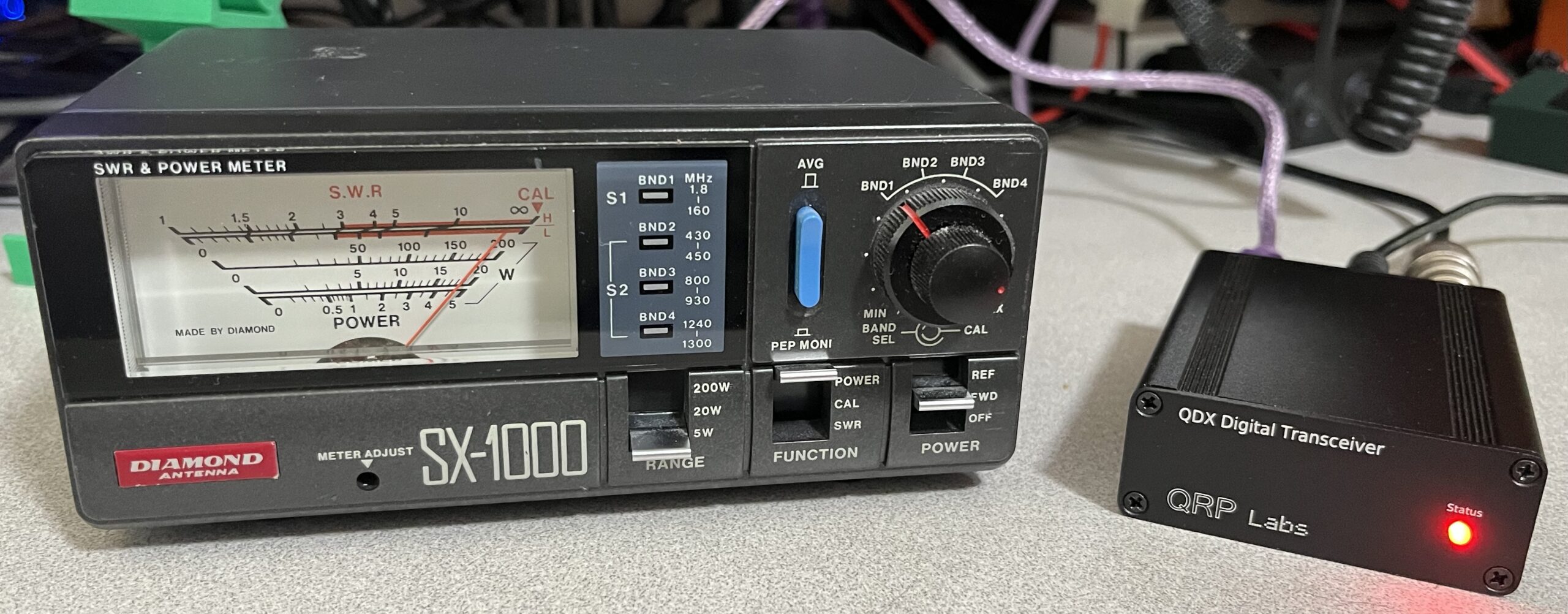
Here is my finished QDX:
I was anxious to test it out. I have a 40 meter inverted V antenna which is resonant in the CW/Digital portion of the band. I followed the instructions in the operating manual to set it up for WSJT-X on my Mac. I figured out what the serial device name was and configured that and the audio devices into WSJT-X. Setting the power slider to MAX and pressing TUNE, I was saw 5 watts output!
I made a few contacts on 40 without any problems. It was very gratifying after the day of building to see it work as advertised.
I don’t have a resonant antenna for 20, so I connected a dummy load to the QDX through an SWR meter. To my dismay, there was zero output when I pressed TUNE. Instead, I saw two flashes of the LED every few seconds. The manual indicated this means there is low audio input to the device. It turns out that when you press TUNE on WSJT-X, the power slider recalls a previous TUNE power setting which wasn’t set to MAX. Adjusting it to MAX caused the QDX to output 5 watts. Everything works as it should.
This is a really nice one or two day project to build and operating it is very satisfying. I highly recommend QRP Labs kits if you’re looking for a moderately challenging project and a lot of operating fun.
I had so much fun building this one, and other kits from QRP Labs that I went back and ordered the QMX 5-band multi-mode transceiver and the VFO/Signal Generator kits.
Leave a Reply